

FD62 Four-needle Six-thread Flat Seamer Feed-off-the-arm sewing machine
Complete Diagram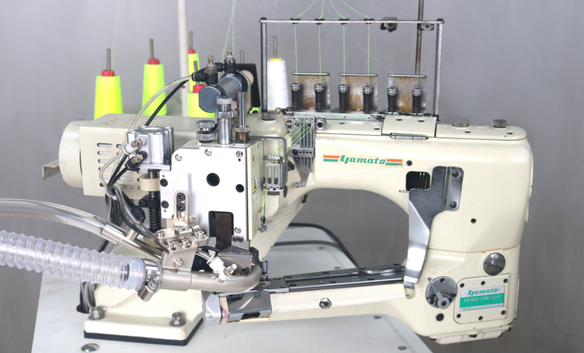
Spare Parts Composition
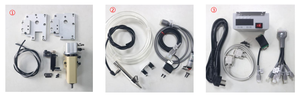
① Cutter assembly
②Suction pipe, light eye switch, manual switch assembly
③Controller, transfer wire, motor signal wire
④ Chopped Cloth suction, knee switch
⑤ Solenoid valve assembly
⑥ Fixed knife protective cover,guide plate, spring gauge
⑦ Dust collection components
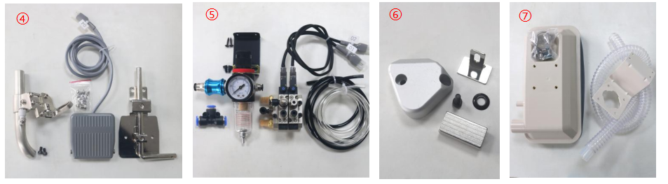
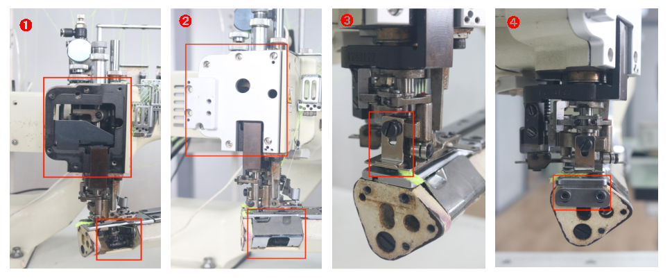
Knife Assembly Installation Diagram
➊:Remove the lower cover and looper cover
➋:Install the special cover of the knife assembly and the looper cover
➌:Install the presser foot presser plate.
➍:Install the fixed blade, the upper edge of the blade is flush with the needle plate
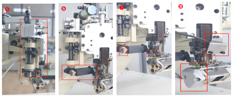
➎:Install the movable knife assembly
➏:Install the movable tool holder and angle gauge. The tape surface is parallel to the fixed blade in the direction of the machine needle
➐:Install the movable blade, adjust the spring screw to adjust the pressure of the movable knife and the fixed knife, so that the cutting line is sharp
➑:Install photocell switch and fixed knife protective cover.
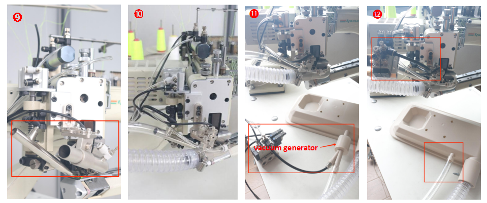
➒:Install suction tubes of chopped cloth & thread ends suction tubes
➓:Install the dust suction device, controller and solenoid valve assembly under the table.
⓫:The connection between the thread ends suction tube and the air pipe (一):The vacuum generator is used for the thread ends suction tube, the suction is strong and the effect is obvious (this method is recommended)
⓬:The connection between the thread ends suction tube and the air pipe (一):With the pipe on the blow, suction is small, the effect is not obvious
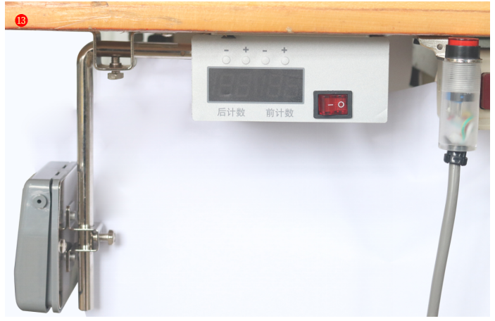
⓭:Install jog switch, knee switch
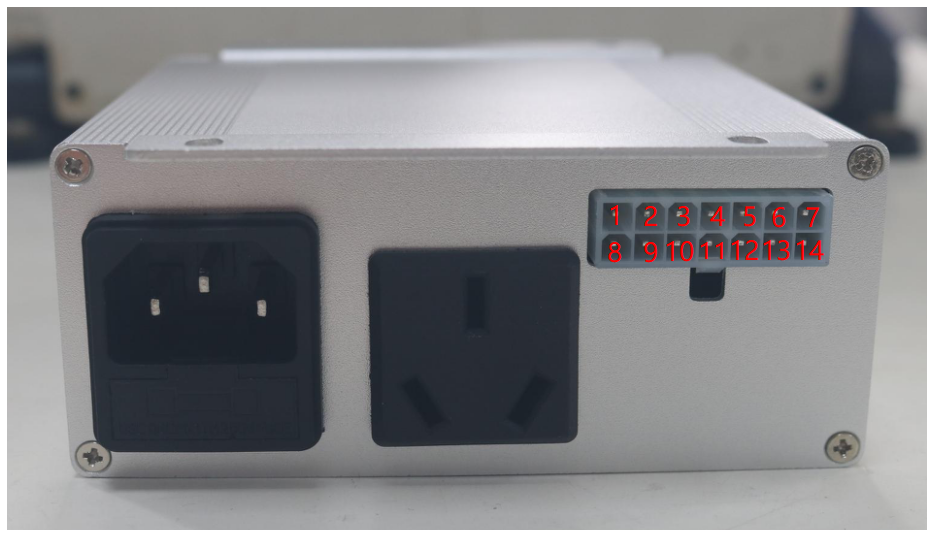
Wiring Diagram
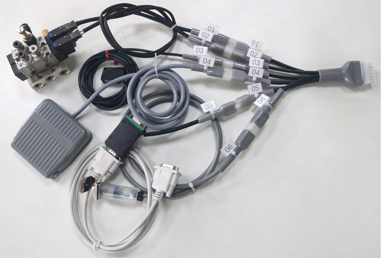
Label 01 : Knife group connection (insert 4mm tube for the knife group solenoid valve)
Label 02: Thread end Suction connection (insert 6mm tube as suction head solenoid valve)
Label 03: Optical eye switch
Label 04: Knee switch
Label 05: Motor signal connection
Label 06: manual switch (manual switch is on, the red light is on, the scissors are off, the red light is flashing, semi-automatic, and the red light is off, the scissors are fully automatic
Controller Instructions
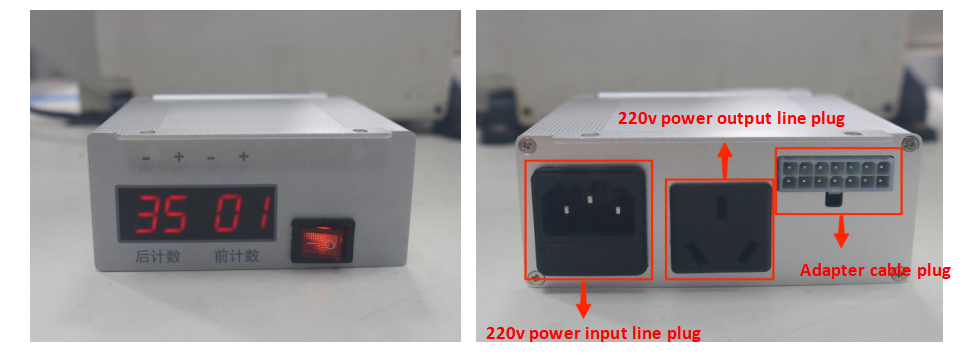
1:Adjust the length of the front and rear thread ends by adjusting the number of front and rear stitches on the controller
2:When the current stitch value is “00″, the front scissors are closed, and when the front stitch number is “1-99″, adjust the length of the front thread end. The larger the value, the shorter the thread end.
3:When the value of the rear needle is “00″, the rear front knife is closed. When the number of rear needles is “1-99″, adjust the length of the rear thread end. The smaller the value, the more thread end.
1+8=scissors 3+10=thread end suction 2+9+4+5=manual switch
5+11=knee switch 6+7=motor signal
12+13+14=light eye signal (12 is negative pole, 13 yellow is output, 14 brown is positive pole)
Post time: Feb-28-2023